GeoArray vertical installation
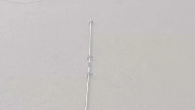
This guide describes the procedure for assembling and deploying the GeoArray for vertical installation in a 70 mm OD inclinometer casing.
Required accessories
Ensure that the following accessories are available before installation:
- Left Guide Wheels
- Right Guide Wheels
- Borehole Cap
- Hex Nut
- Self-tapping Screws
- Angle Gauge
- Borehole Collar Protective Cover
Assembling the GeoArray
1Install the guide wheels
Position the guide wheel into the slot on the stainless-steel tube.
- Secure one side of the guide wheel into the slot.
- Press the opposite side into place by hand or using a pair of small pliers.
- Ensure that the guide wheel is fully seated in the slot.
NoticeInstall two (2) guide wheels per sensor segment.
2Install the borehole cap
- Position the borehole cap onto the sensor head.
- Install the supplied hex nut onto the threaded section.
- Tighten the hex nut until the borehole cap is firmly secured.
Ensure that the borehole cap is properly fastened before deployment. Once the guide wheels and borehole cap have been installed, the GeoArray is ready for deployment.
Deploying into the casing
3Prepare the inclinometer casing
The GeoArray is designed to be installed inside a 70 mm outer diameter (OD) inclinometer casing.
4Insert the GeoArray into the casing
- Slowly insert the GeoArray into the inclinometer casing.
- Begin the insertion from the tail end of the sensor assembly.
- Lower the assembly gradually to prevent damage to the sensor or guide wheels.
5Align the guide wheels
- Ensure that the guide wheels are properly aligned with the guide grooves inside the inclinometer casing.
- The guide wheels must engage with the casing grooves to ensure correct sensor orientation and accurate measurements.
Sensor orientation and monitoring direction
After installation, the instrument’s X-axis direction represents the positive measurement direction. Depending on the monitoring requirements, the instrument’s X-axis may not be aligned with the actual monitoring direction. Therefore, the angular offset between these two directions must be measured.
6Install the angle gauge
- Position the supplied angle gauge around the instrument.
- Align the X-MARK on the angle gauge with the X-MARK on the instrument.
ImportantAccurate alignment of both X-MARK references is essential for obtaining a correct angle measurement.
7Measure the angle
- Determine the angular difference between the instrument’s X-axis and the required monitoring direction.
- For example, if the measured angle is 268°, record this value for configuration.
8Enter the angle value into Nimbus
- Open the Ackcio Nimbus App.
- Navigate to the corresponding GeoArray device configuration.
- Enter the measured angle value.
- Save the configuration.
After the angle value has been entered, the GeoArray system automatically applies a coordinate transformation algorithm. This algorithm converts measurements from the instrument’s X-axis positive direction to the actual monitoring or displacement direction.
NoticeIncorrect angle configuration may result in displacement being reported in the wrong direction.
Finishing the borehole
9Install the protective cover
After completing the orientation configuration:
- Place the borehole collar protective cover over the inclinometer casing.
- Ensure that the sensor cable exits the cover without being pinched or excessively bent.
10Secure the protective cover
- Insert the supplied self-tapping screws into the mounting holes.
- Tighten the screws until the protective cover is securely attached to the inclinometer casing.
ImportantDo not overtighten the screws. Ensure that the sensor cable maintains an appropriate bend radius, and verify that the cable is not subjected to excessive tension.