FAQ: Specific node types and sensors (Snape 1.0)
Q99What unit of measurement should be used for MDT Sloughmeter sensors?
MDT Sloughmeter sensors output RAW_ADC values only. Select RAW_ADC as the output unit during commissioning.
MDT MPBX sensors are compatible with any output unit available in the Nimbus app.
Q100How does the MDT Sloughmeter integrate with the Ackcio BEAM-DG node?
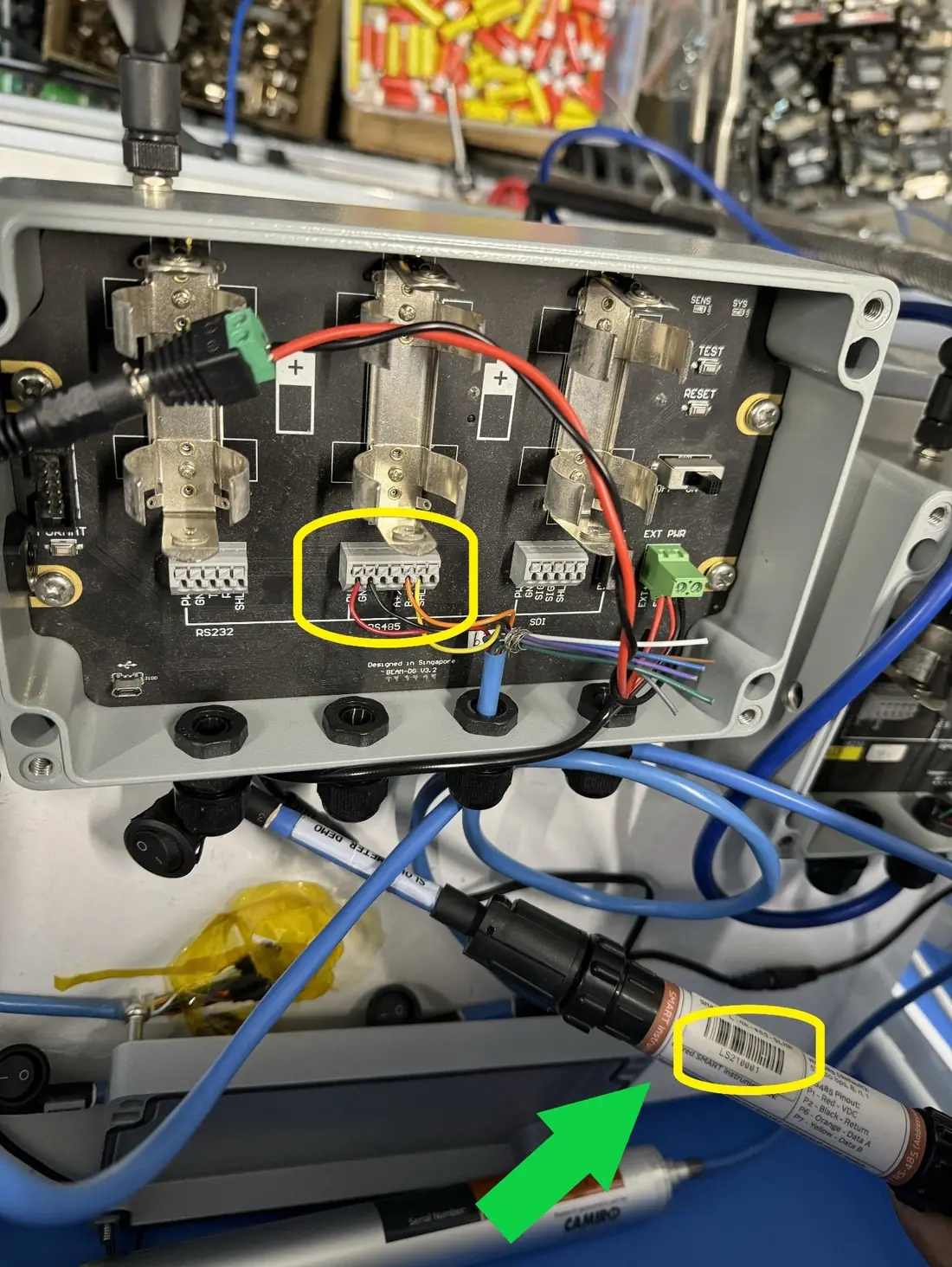
MDT sensors output analogue signals that are converted via a SMARTLINK adapter for integration with the DG node.
- Supports up to 6 addressable SMARTLINK sensors per DG node
- Or 1 non-addressable SMARTLINK sensor per DG node
Refer to the wiring diagram below on which PORT to connect and Sensor Address placement:
Q101What weather stations are compatible with the Ackcio DG node?
- Climavue 50: Highly recommended; wide-range meteorological measurements (SDI-12)
- Maximet (Gill Instruments): Compact, robust weather monitoring (SDI-12)
Q102Can the DG node be powered externally?
Yes: via wall socket or solar panel, the same as the Gateway. A dedicated battery pack (BEAM-BP) is also available for the DG node.
VWS8, ANS4, and DG nodes all support single D-Cell operation; extra slots provide additional runtime.
Q103How many VWS8 channels appear on the Snape Sensor Summary?
Only channels assigned to separate Sensor Groups appear individually. Channels sharing the same Sensor Group show only the first channel in the summary.
Assign unique Sensor Groups per channel if individual visibility in the summary is required.
Q104How do I disable unused channel ports on the VWS8?
Unused ports can be disabled directly in Snape, no recommissioning required. Refer to the guide below:
Q105What is the recommended cable length for Vibrating Wire sensors?
Up to 50 metres (164 ft) is considered safe, provided:
- Cables are properly shielded and grounded
- High-quality, twisted-pair, shielded cable is used
- Minimal EMI exposure at the installation site
Common causes of reading inconsistency beyond 50 m:
- Cable length differences across sensors
- Inconsistent shield grounding (introduces electrical noise)
- Voltage drop across long cable runs (affects thermistor accuracy)
Q106What sensors is the Ackcio system compatible with?
- VW nodes: Strain gauges, load cells, piezometers, crackmeters
- ANS nodes: MEMS tiltmeters, LVDT sensors, pressure cells, MPBX sensors
- DG nodes: Refer to BEAM-DG datasheet for compatible sensor brands
For compatibility of a specific sensor, submit its datasheet to Ackcio support.
Q107Does Ackcio sell sensor-specific connectors?
No. Two alternatives are available:
- Cut the existing connector and wire directly into the node's terminal block.
- Procure the appropriate connector from the sensor manufacturer.
Q108How should the Beam-TM inclinometer accuracy and resolution specs be interpreted?
Accuracy: How close the measurement is to the true value. E.g., ±0.01° at 15° means the reading will fall between 14.99° and 15.01°.
Resolution: The smallest detectable change in angle: a finer resolution means more precise measurement granularity.
Refer to the Beam-TM product datasheet for full specification tables.
Q109How does the Geoarray sensor handle settlement axis, output units, and sign convention?
Settlement axis (horizontal): Z-axis. X-axis corresponds to segment length (e.g., 500 mm or 1000 mm).
Settlement axis (vertical): X & Y-axis. Z-axis corresponds to segment length (e.g., 500 mm or 1000 mm).
Output units: Millimetres (mm). No additional transformation required.
Sign convention: When installed horizontally, set the reference point as Near or Far. When set to Near, the end closest to the node is the fixed reference; displacement is measured relative to it.
Full guide: GeoArray guide.
Q110What are the Measurand ShapeArray power modes and current draw?
- Regular Power Mode → ~1.8 mA per segment
- Low Power Mode → ~0.4 mA per segment
For serial numbers > 700,000, the Low Power Mode value applies by default. To check or change mode, connect via SAARecorder software using an SAA232, SAAFPU, or PDU interface.