Wire and set up a BEAM-AN node
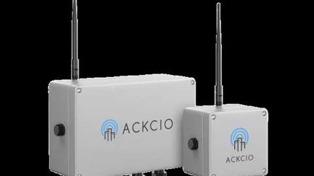 Commissioning videoBEAM-AN-S1: VoltageWatch on YouTube ↗Commissioning videoBEAM-AN-S4: Voltage, potentiometer, current loopWatch on YouTube ↗
Analogue Node: Voltage / Current Loop / Resistance Sensors
The BEAM-AN (Analogue Node) is compatible with a wide range of sensors that produce analogue output signals, including tilt sensors, water level sensors, load cells, and pressure transducers. Supported output types include:
- Voltage output (0-5,0-12,0-24V)
- Current loop output (4-20mA)
- Resistance-based output (e.g., thermistors, potentiometers)
Step 1: Wiring Your Sensor to the BEAM-AN Node
Connect your sensor's wires to the BEAM-AN Node's terminal blocks as shown in the diagrams below. Match the wire colours and functions to the labelled terminal positions on the node.
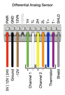
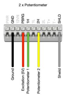
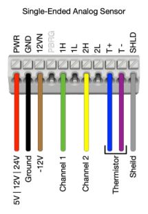
BEAM-AN Wiring Configurations: Voltage, Current Loop, Resistance, and Thermistor
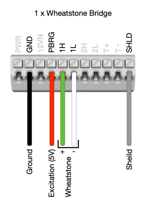
BEAM-AN Additional Wiring Reference
Step 2: Configuring the BEAM-AN Node in Nimbus 2.0
After wiring your sensor, launch the Ackcio Nimbus 2.0 app and follow the steps below on the Setup Sensor page.
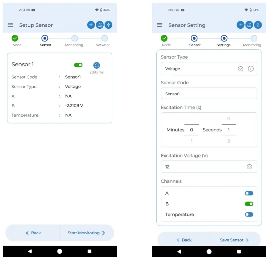
Nimbus 2.0, Sensor Type selection (left, click the box) and Sensor/Channel configuration and Save Sensor screen (right)
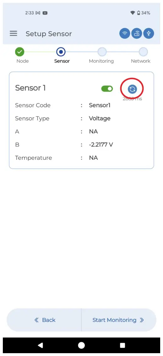
Nimbus 2.0, Triggering live reading from sensor by pressing the Blue Refresh Icon
1. On the Setup Sensor page in the Ackcio Nimbus 2.0 app, tap on Sensor 1 to begin configuration.
2. Tap Sensor Type and select the appropriate type for your sensor (e.g., Current Loop, Voltage, Wheatstone, ensure Wheatstone adaptor is fixed, potentiometer).
3. Tap Sensor Code and enter a meaningful name for your sensor (e.g., 'TiltSensor_A1').
4. Tap Excitation Time and select the appropriate period. For most sensors, 1 to 2 seconds is sufficient. Refer to your sensor datasheet for the exact specification. Note: excitation times beyond 2 seconds will increase battery consumption.
5. Tap Excitation Voltage and select the appropriate voltage as specified in your sensor datasheet.
6. Enable or disable channels as required. Enable Channel A if your sensor has one analogue output; enable both A and B if it has two. Disable the Temperature channel if your sensor has no thermistor output.
7. Tap Save Sensor. The SENS LED on the node will begin blinking, this confirms the node is actively reading the sensor.
8. Tap the Blue Refresh icon to trigger a live test reading. Verify that the values are within the expected range for your sensor.
9. Once satisfied with the readings, tap Start Monitoring to proceed.
10. You will be prompted to clear the Node's flash memory. Toggle ON to clear historical data if this is a fresh commissioning.
11. Set your desired sampling rate and tap Save. The SYS LED will resume blinking once monitoring begins.