Node overview: battery, buttons, ports and LEDs (Standalone)
Node overview
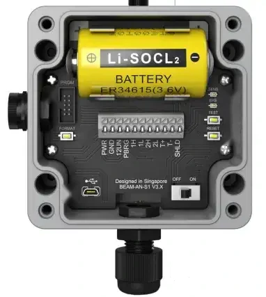
Your Ackcio Nodes will act as data loggers with radio transmitters, allowing for the reading of sensors and the transmission of those sensor readings to the Gateway. This section will cover the hardware of our Nodes:
 1234567891011
Inside a BEAM-AN-S1 node. The numbers match the sections below.
12Node battery and power switch
Your Node will contain a battery holder meant for a D cell battery. Our Nodes are designed to be used with a ER34615 battery or another battery with similar specifications. This battery will provide your Node and its connected sensor(s) with power to function. The only exception to this would be our BEAM-DG Nodes, which have the option of powering their sensors via an external power source.
Your Node will also contain a power switch that is used to turn the Node on or off. We would recommend only turning the Node on when you want to commission it or when the Node is within range of its Gateway. Should the Node be unable to connect to its Gateway, it will constantly drain its battery while searching for it.
CautionIf a Node’s battery is completely drained, the Node’s HPC capacitor can be fully discharged if it is left running. Once this happens, the Node will not work until the capacitor is replaced. We would thus strongly recommend against leaving your Nodes powered when they are out of range of or not commissioned to a Gateway.
3Antenna
Your Node’s packaging will contain an antenna, which is required for your Node to communicate with the other devices via radio. GW, nodes including TM-L use the same short black antenna with high gain.
StandaloneNot needed in Standalone mode: standalone nodes run without an antenna.
4Format button
The Format button’s primary function is to manually clear your Node’s flash memory of data. This can be useful when you want to remove test or unneeded data from a Node before deploying it. To clear your Node’s memory, press and hold down the Format button for 5 seconds while your Node is on. You will then see your Node’s SYS LED turn solid and blink rapidly after, indicating that the Node was formatted successfully.
56Reset and Test button
The Reset button’s primary function is to manually restart your Node. This can be used to set a Node back to its default state or to set a Node in pairing mode. To do so, press the Reset button while your Node is on. You will then see your Node’s SYS LED start blinking, indicating it has restarted and is scanning for neighboring devices.
The Test button’s primary function is to immediately trigger a sensor reading on your Node. This can be used to confirm your Node is set up correctly, or to test your Node’s connection to the Gateway. To do so, press the Test button while your Node is on. You will then see your Node’s SENS LED start blinking, indicating that it’s reading the connected sensor.
The Test button is also used to put your Node into Update mode. This is required when updating your Node’s firmware. To do so, hold down your Node's Test button and then Reset button and take your fingers off from Reset and then Test and immediately trigger Firmware Update button on the Nimbus App
78Connector block and cable gland
Your Node will have connector blocks which you can wire your sensors to. Each connector will accept a single sensor wire, which can be prepared by stripping a short length of insulation.
9Debugger port
The debugger port’s primary function is to allow you to update your Node’s firmware with your debugger and OTG adapter. This port is for the troubleshooting of Ackcio team alone and not meant for clients.
10Micro USB port
The Micro USB port’s primary function is to allow you to commission your Node with your Android device (see Connecting your Android device to a node). For TM-L you would be expecting a USB C port instead.
11Node LEDs
The SENS LED’s primary function is to indicate when the Node is reading the sensor connected to it. When a sensor reading is triggered, the SENS LED will blink a few times rapidly.
The SYS LED’s primary function is to indicate the Node’s status. When the Node is first powered ON, you will see the SYS LED blinking to indicate that the Node is powered and is scanning for neighboring devices. When the Node LED stops blinking, it indicates that the Node has joined the Gateway’s network successfully and will begin transmitting sensor readings to it.